After completing the CAD for prototype 4, I realized the top of the structure wasn’t compliant to the CubeSat requirements – the top, like the bottom, requires specific “posts” for the interface to either the launch provider’s system or neighbouring CubeSats in the same launcher package.
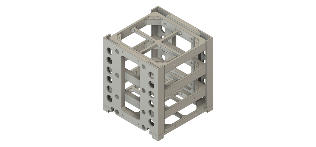
Prototype 4 (abandoned)
There were things to like about this design concept, especially the Y-minus and Y-plus sides as identical parts that provided vertically-oriented compression strength. This approach eliminated the mounting points on the outside rails, making a smooth and simple interface point with the launch provider’s system. This design also allows for flexible arrangement of the inside component trays.
This led to prototype 5, retaining the key concepts from prototype 4 but changing how the top structure was arranged.
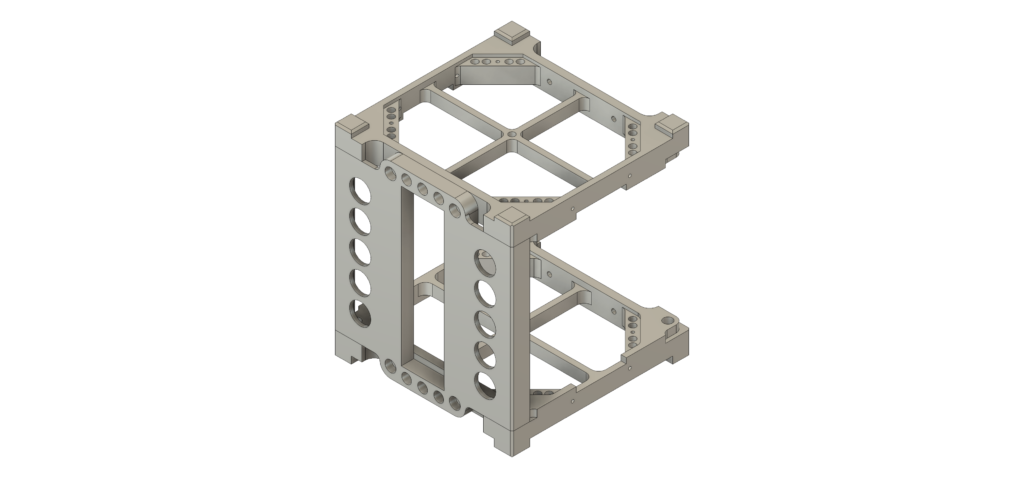
Protype 5 (abandoned)
This design concept resolved the issue of the top plate, creating “post” interface points as required by the CubeSat design guide. However after getting the CAD to this point I was dissatisfied with some of the dimensions of the all sides, either being too thin or too thick to my liking. I don’t have a good way to simulate the strength of the structure (at least not yet) so a lot of this portion of the design process is going by instinct.
Next up: prototype 6. This design concept is really promising, enough so that I completed the entire four sides and also created circuit boards in KiCad to get a sense of the whole structure.
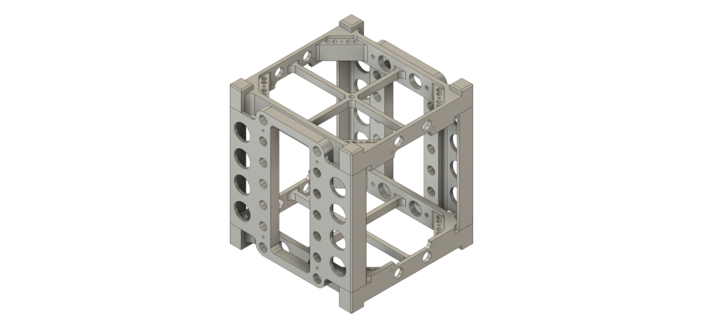
Prototype 6
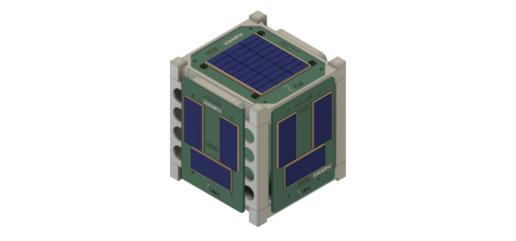
Prototype 6 with sample circuit boards
This design concept is starting to look very good. Still need to design the internal component trays, but given that the Z-minus and Z-plus side each has an outside and inside board it might only be necessary for a single tray in the middle of the stack.