The initial prototype was an experiment in designing for a compact structure, following the size constraints from the CubeSat Design Specification. Designed in Autodesk Fusion 360, printed in PETG.
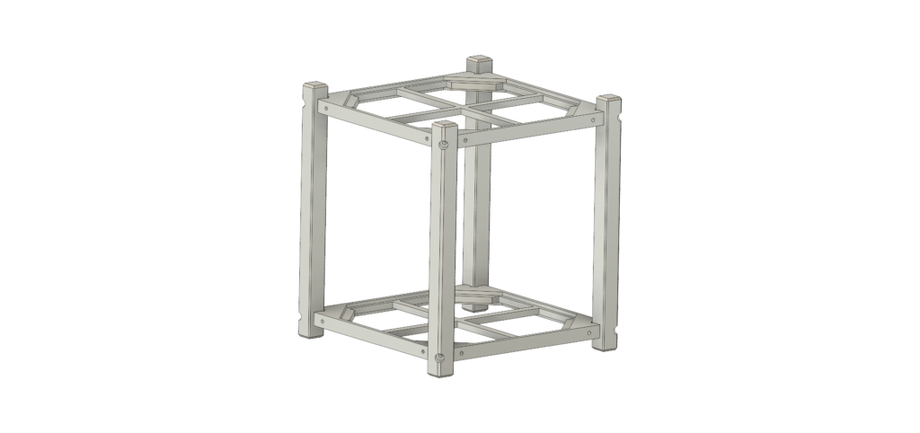
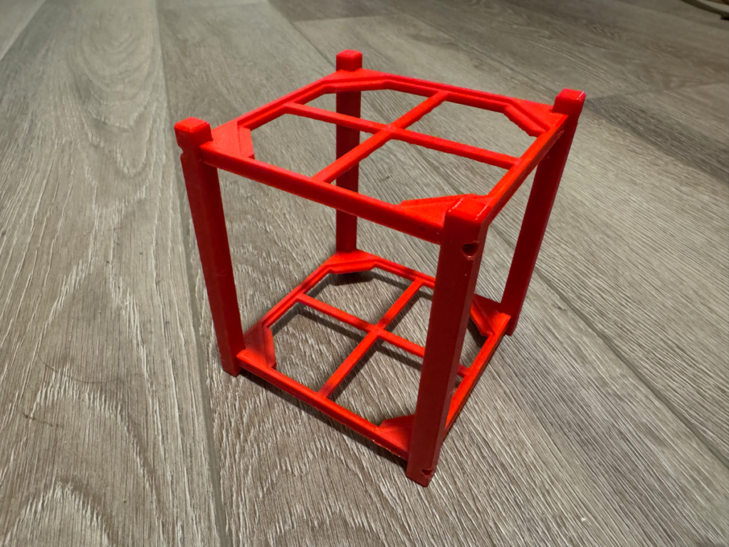
This iteration helped explore a few different ideas, such as the horizontal component trays that would allow a circuit board to be mounted on each side, with interconnects back-to-back from each board. But once printed it was obvious the spacing between each board would be insufficient for regular header/socket connectors.
Having the physical model also helped with visualizing how these parts could be manufactured efficiently, and it was obvious some design changes would make it easier to machine these parts myself if necessary.
Also decided using M2 bolts for connecting the rails to the component trays would not be sufficient.
Next iteration will include the following improvements:
- Design the rails and component trays that can be machined on a small home milll such as a Sherline with CNC with a 4mm endmill
- Increase the size of the rails to 10mm (from 8.5mm)
- Avoid the corner “slot” in the component tray where it interfaces with the rails, as this is likely difficult to machine; opt for a larger bevel on the inside of each rail to achieve the same fit but easier to machine
- Use M3 bolts to fasten the rails to the component trays
- Increase the height of the component trays such that the spacing between the PCB boards will be sufficient for pin and socket connections
- All threaded holes should be “full depth” for simpler drilling and hand tapping